Some Known Incorrect Statements About Wedge Barriers
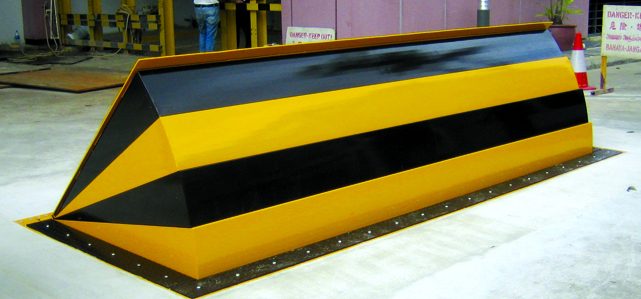
In the complying with discussion, recommendation is made to a surface of a structure to which the wedge-style barrier is placed. In the illustrated embodiments, the upper side of the support is substantially flush with the surface of the structure. In such personifications, the wedge-style barrier might be placed straight to the surface of the foundation. However, in other embodiments, the upper side of the support may be a little increased above the surface area of the foundation or slightly recessed below the surface of the foundation. 1 is a front perspective sight of an embodiment of a surface-mounted wedge-style obstacle 10. As shown, the barrier 10 is placed to a surface area 12 of a foundation 14(e. g., a superficial foundation ). For instance, the foundation
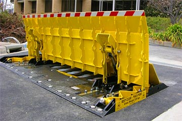
14 and the surface area 12 to which the barrier 10 is safeguarded might be made from concrete - Wedge Barriers. 2, the barrier 10 is mounted to or consists of an anchor or subframe (e. g., anchor 30 displayed in FIG. 2 )safeguarded underneath the surface area 12. The bather 10 might be bolted to the support or protected to the anchor by other mechanical bolts. In the detailed personification, the barrier 10 consists of a wedge plate 16, that includes a portion that is considerably parallel with the surface 12 when the barrier 10 remains in the retracted placement. In other words, automobiles or people may pass over the obstacle 10 when the barrier 10 is in the retracted position and experience small elevation loved one to the surface 12 while on the obstacle 10. As gone over thoroughly below, when the obstacle 10 is in the deployed position, the wedge plate 16 is held and sustained in an elevated setting by a lifting mechanism of the obstacle 10. Furthermore, the elements 18 may be bolted or otherwise mechanically coupled to each other. In this fashion, repair work or substitute of several parts 18 may be simplified and streamlined. That is, repair work or substitute of solitary components
18 might be done quicker, quickly, and cost effectively. FIG. In certain embodiments, the support 30 may be a steel framework consisting of plates, beam of lights(e. g., I-beams ), and/or other structures that are protected within the foundation 14, which may be concrete. At the surface 12, an upper side 28 of the anchor 30 might be at the very least partly subjected
, therefore allowing the accessory of the obstacle 10 to the anchor 30. g., threaded openings)in one or more beams or plates of the support 30 may be exposed to the surface area 12. In this way, screws 32 or various other mechanical fasteners may be utilized to safeguard the barrier 10 to the support 30. As the obstacle 10 is placed to the surface area 12 of the structure 14, collection of particles and various other product under the obstacle might be reduced, and elements of the bather 10 might not be subjected to below grade settings. As shown by referral numeral 52, the lifting system 50 consists of parts disposed beneath the wedge plate 16. For instance, the parts 52 under the wedge plate 16 may consist of an electromechanical actuator, a webcam, several web cam surface areas, etc. In addition, the lifting device 50 includes a spring setting up 54
The springtime rod 58 is coupled to a web cam(e. g., cam 80 shown in FIG. 4) of the training mechanism 50. The springtimes 60 disposed regarding the spring rod 58 are kept in compression by springtime sustains 62, consisting of a dealt with spring support 64. That is, the fixed springtime support 64 is fixed about the foundation 14 and the rest of the bather 10.
The Basic Principles Of Wedge Barriers
The staying force used to
the cam camera deploy the wedge plate 16 may might provided supplied an electromechanical actuator 84 or other actuator. The spring setting up 54 and the actuator 84(e. Wedge Barriers. g., electromechanical actuator)may run together to translate the webcam and lift the wedge plate 16.
As pointed out over, the springtime assembly 54 exerts a continuous force on the webcam, while the electromechanical actuator may be managed to put in a variable force on the camera, thus making it possible for the lifting and reducing( i. e., releasing and pulling back )of the wedge plate 16. In specific embodiments, the consistent pressure applied by the spring setting up 54 might be flexible. g., electromechanical actuator) is handicapped. As will be valued, the springtime setting up 54 might be covered and secured from particles or other aspects by a cover plate(e. g., cover plate 68 shown in FIG. 4) that might be considerably flush with the raised surface area 38 of the foundation 14. As discussed over, in the deployed placement, the wedge plate 16 serves to block accessibility or travel beyond the barrier 10. The obstacle 10(e. g., the wedge plate 16 )may block pedestrians or automobiles from accessing a home or pathway. As discussed over, the barrier 10 is connected to the anchor 30 safeguarded within the foundation 14,
front braces 71. Consequently, the linkage settings up 72 may pivot and revolve to allow the collapse and expansion of the link assemblies 72 during retraction and implementation of the bather 10. The linkage settings up 72 reason movement of the wedge plate 16 to be restricted. As an example, if a lorry is taking a trip towards the deployed wedge plate 16(e. As an example, in one circumstance, over here the security legs 86 might be expanded duringupkeep of the obstacle 10. When the security legs 86 are released, the safety legs 86 support the weight of the wedge plate 16 versus the surface 12. As an outcome, the training system 50 might be shut off, serviced, gotten rid of, replaced, and so forth. FIG. 5 is partial perspective view of a personification of the surface-mounted wedge-style obstacle 10, illustrating the cam 80 and the web cam surface areas 82 of the lifting system 50. Particularly, 2 camera surfaces 82, which are referred to as reduced cam surface areas 83, are positioned below the camera 80. The reduced webcam surface areas 83 might be fixed to the surface 12 (e. For instance, the lower web cam surface areas 83 and the placing plate 85 may create a solitary item that is safeguarded to the support 30 by screws or other mechanical fasteners. In addition, 2 cam surfaces 82, which are described as top web cam surface areas 87, are placed over the cam 80 and combined to (e. In various other embodiments, interfering layers or plates might be placed between the surface 12 and the lower web cam surface areas 83 and/or the wedge plate 16 and the top cam surface areas 87 As discussed over, the webcam
80 converts along the webcam surface areas 82 when the wedge plate 16 is raised from the pulled back setting to the deployed setting. In addition, as stated over, the spring assembly 54 (see FIG. 3 )may give a pressure acting upon the cam 80 in the instructions 102 through spring pole 58, which may minimize the pressure the electromechanical actuator 84 is needed to put on the camera 80 in order to actuate and Check Out Your URL raise the wedge plate 16. 1 )to the released position(see FIG. 4). As revealed, the webcam 80 includes track wheels 104(e. g., rollers), which contact and equate along the cam surfaces 82 during procedure.
Comments on “How Wedge Barriers can Save You Time, Stress, and Money.”